Introduction
The hardware configuration when using multiple 1-Wire temperature sensors like the DS1820 is very simple, as illustrated in the block diagram below. A single-wire bus is used for communication between the microcontroller and the temperature sensor. It is also possible to power the devices direclty via this 1-Wire bus. An almost unlimited number of 1-WireTM devices can be connected to the bus because each device has a unique 64-bit ROM code identifier which is used to address each sensor

Temperature measurement using DS1820 sensor. Use of ‘1-wire’ protocol...
Temperature measurement is one of the most common tasks performed by the microcontroller. A DS1820 sensor is used for measurement here. It is capable of measuring temperature in the range of -55 °C to 125 °C with 0.5 °C accuracy. For the purpose of transferring data to the microcontroller, a special type of serial communication called 1-wire is used.
Due to a simple and wide use of these sensors, commands used to run and control them are in the form of functions stored in the One_Wire library. There are three functions in total:
- Ow_Reset is used for reseting sensor;
- Ow_Read is used for receiving data from sensor; and
- Ow_Write is used for sending commands to sensor.
Concretely, you don’t have to study documentation provided by the manufacturer in order to use this sensor. It is sufficient to copy some of these functions in the program.
OneWire Library
The OneWire library provides routines for communication via the Dallas OneWire protocol, e.g. with DS18x20 digital thermometer. OneWire is a Master/Slave protocol, and all communication cabling required is a single wire. OneWire enabled devices should have open collector drivers (with single pull-up resistor) on the shared data line.
Slave devices on the OneWire bus can even get their power supply from data line. For detailed schematic see device datasheet.
Some basic characteristics of this protocol are:
- single master system,
- low cost,
- low transfer rates (up to 16 kbps),
- fairly long distances (up to 300 meters),
- small data transfer packages.
Each OneWire device has also a unique 64-bit registration number (8-bit device type, 48-bit serial number and 8-bit CRC), so multiple slaves can co-exist on the same bus.
Note: Oscillator frequency Fosc needs to be at least 8MHz in order to use the routines with Dallas digital thermometers.
External dependencies of OneWire Library
This variable must be defined in any project that is using OneWire Library: | Description: | Example : |
extern sfr sbit bdata OW_Bit; | OneWire line. | sbit OW_Bit at P2_7_bit; |
Library Routines
Ow_Reset
Prototype | unsigned short Ow_Reset(); |
Returns |
|
Description | Issues OneWire reset signal for DS18x20. Parameters :
|
Requires | Devices compliant with the Dallas OneWire protocol. Global variable OW_Bit must be defined before using this function. |
Example | // Issue Reset signal on One-Wire Bus Ow_Reset(); |
Ow_Read
Prototype | unsigned short Ow_Read(); |
Returns | Data read from an external device over the OneWire bus. |
Description | Reads one byte of data via the OneWire bus. |
Requires | Devices compliant with the Dallas OneWire protocol. Global variable OW_Bit must be defined before using this function. |
Example | // Read a byte from the One-Wire Bus unsigned short read_data; ... read_data = Ow_Read(); |
Ow_Write
Prototype | void Ow_Write(char par); |
Returns | Nothing. |
Description | Writes one byte of data via the OneWire bus. Parameters :
|
Requires | Devices compliant with the Dallas OneWire protocol. Global variable OW_Bit must be defined before using this function. |
Example | // Send a byte to the One-Wire Bus Ow_Write(0xCC); |
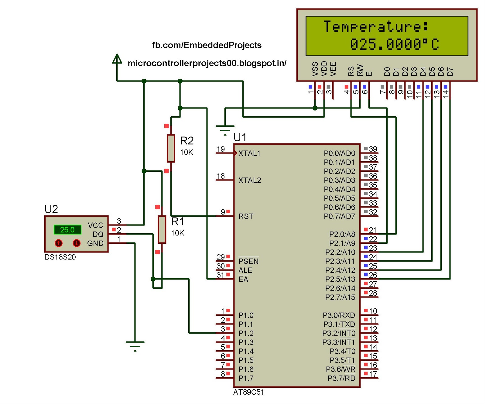
Circuit
Code
This example reads the temperature using DS18x20 connected to pin P1.2. After reset, MCU obtains temperature from the sensor and prints it on the Lcd. Make sure to pull-up P1.2 line and to turn off the P1 leds.
// LCD module connections
sbit LCD_RS at P2_0_bit;
sbit LCD_EN at P2_1_bit;
sbit LCD_D4 at P2_2_bit;
sbit LCD_D5 at P2_3_bit;
sbit LCD_D6 at P2_4_bit;
sbit LCD_D7 at P2_5_bit;
// End LCD module connections
// OneWire pinout
sbit OW_Bit at P1_2_bit;
// end OneWire definition
// Set TEMP_RESOLUTION to the corresponding resolution of used DS18x20 sensor:
// 18S20: 9 (default setting; can be 9,10,11,or 12)
// 18B20: 12
const unsigned short TEMP_RESOLUTION = 9;
char *text = "000.0000";
unsigned temp;
void Display_Temperature(unsigned int temp2write) {
const unsigned short RES_SHIFT = TEMP_RESOLUTION - 8;
char temp_whole;
unsigned int temp_fraction;
// check if temperature is negative
if (temp2write & 0x8000) {
text[0] = '-';
temp2write = ~temp2write + 1;
}
// extract temp_whole
temp_whole = temp2write >> RES_SHIFT ;
// convert temp_whole to characters
if (temp_whole/100)
text[0] = temp_whole/100 + 48;
else
text[0] = '0';
text[1] = (temp_whole/10)%10 + 48; // Extract tens digit
text[2] = temp_whole%10 + 48; // Extract ones digit
// extract temp_fraction and convert it to unsigned int
temp_fraction = temp2write << (4-RES_SHIFT);
temp_fraction &= 0x000F;
temp_fraction *= 625;
// convert temp_fraction to characters
text[4] = temp_fraction/1000 + 48; // Extract thousands digit
text[5] = (temp_fraction/100)%10 + 48; // Extract hundreds digit
text[6] = (temp_fraction/10)%10 + 48; // Extract tens digit
text[7] = temp_fraction%10 + 48; // Extract ones digit
// print temperature on LCD
Lcd_Out(2, 5, text);
}
void main() {
Lcd_Init(); // Initialize LCD
Lcd_Cmd(_LCD_CLEAR); // Clear LCD
Lcd_Cmd(_LCD_CURSOR_OFF); // Turn cursor off
Lcd_Out(1, 1, " Temperature: ");
// Print degree character, 'C' for Centigrades
Lcd_Chr(2,13,223); // different LCD displays have different char code for degree
// if you see greek alpha letter try typing 178 instead of 223
Lcd_Chr(2,14,'C');
//--- main loop
do {
//--- perform temperature reading
Ow_Reset(); // Onewire reset signal
Ow_Write(0xCC); // Issue command SKIP_ROM
Ow_Write(0x44); // Issue command CONVERT_T
Delay_us(120);
Ow_Reset();
Ow_Write(0xCC); // Issue command SKIP_ROM
Ow_Write(0xBE); // Issue command READ_SCRATCHPAD
temp = Ow_Read();
temp = (Ow_Read() << 8) + temp;
//--- Format and display result on Lcd
Display_Temperature(temp);
Delay_ms(500);
} while (1);
}
.
I honestly think you would have fully sold me on the idea had you been able to back up your premis with a substantial bit more solid facts.
ReplyDeleteChhipa Medical
Fantastic Post! Lot of information is helpful in some or the other way. Keep updating.digital thermometer
ReplyDelete89C51 Based Digital Thermometer Using Ds1820 >>>>> Download Now
ReplyDelete>>>>> Download Full
89C51 Based Digital Thermometer Using Ds1820 >>>>> Download LINK
>>>>> Download Now
89C51 Based Digital Thermometer Using Ds1820 >>>>> Download Full
>>>>> Download LINK 5E